Currency
|
|
Title:
|
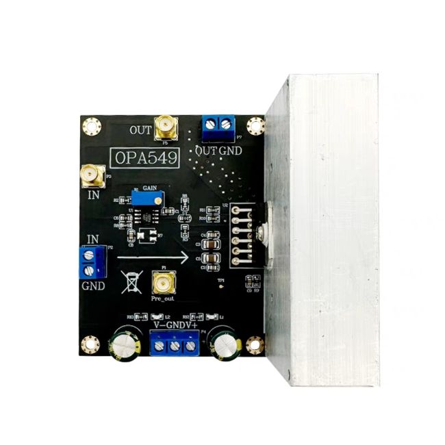
OPA549 Audio Power Amplifier 8A Current Drives High-Voltage Current Amplifier | ||
| Specifications: |
Module model: 0P549
Module type: Low frequency power amplifier
Input signal form: single ended
Input voltage range: 2Vpp (MAX) (usually within the power supply)
Module input impedance: 10K ohms
Module power supply voltage: ± 4V~± 30V
Module power supply current: ± 8A (high output current requires high power supply current)
Module output impedance: low impedance
Output voltage range: 54Vpp (MAX) (under positive and negative 30V power supply)
Output current: 8A (MAX) (module has set 5A current limit)
Output power: 100W (MAX)
Module gain: 3~33 times adjustable (potentiometer adjustment, clockwise adjustment small, counterclockwise adjustment large)
Input offset voltage: 1mV (MAX)
Input offset drift: 2uV/C (MAX)
Input bias current: 125nA (MAX)
Input voltage noise: 35nV √ Hz (1KHz)
Module protection: None (no reverse connection protection, infinite current protection)
Module specifications: 86 * 81 * 52mm (length * width * height PCB size)
Module heating: equipped with heat sinks (forced air cooling is required for high current)
Module heating factor: Input/output voltage too high or module damage
|
||
| Module usage precautions |
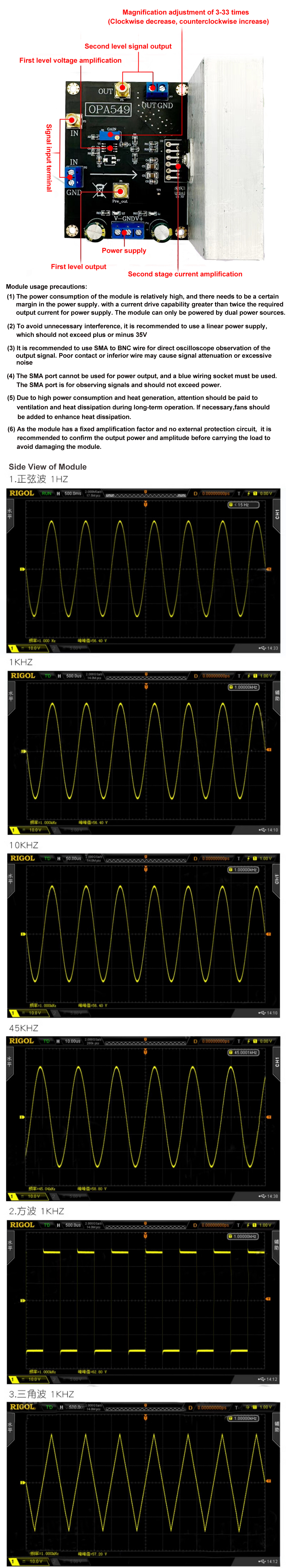
(1) The power consumption of the module is relatively high, and the power supply needs to have a certain margin. It is recommended to use a power supply with a current drive capability greater than twice the required output current. The module can only be powered by dual power supplies.
(2) To avoid unnecessary interference, it is recommended to use a linear power supply, which should not exceed plus or minus 35V.
(3) It is recommended to use SMA to BNC wire for direct oscilloscope observation of the output signal. Poor contact or inferior wire may cause signal attenuation or excessive noise.
(4) The SMA port cannot be used for power output, and a blue wiring socket must be used. The SMA port is for observing signals and should not exceed power.
(5) Due to high power consumption and heat generation, attention should be paid to ventilation and heat dissipation during long-term operation. If necessary, additional fans should be added to enhance heat dissipation.
(6) As the module has a fixed amplification factor and no external protection circuit, it is recommended to confirm the output power and amplitude before carrying the load to avoid damaging the module.
Frequently Asked Questions:
Q: Is the magnification fixed? How do I need to adjust it?
A: The default magnification of the module is 33 times. If you need to adjust the magnification, you can only replace the resistor on the board. The resistor package is 0805, and the calculation formula has been provided in the parameter details.
Q: Can modules directly drive coils?
A: The module can drive the coil, but the internal resistance of the coil is required to be greater than 4 ohms. If it is less than 4 ohms, a power resistor needs to be connected in series, otherwise the module may be damaged.
Q: Can modules amplify square waves or pulses? What is the module bandwidth?
A: The module can amplify low-frequency square waves or pulses. As an audio amplifier, the total bandwidth is not high, and signals within 100K can be amplified. The module is compatible with DC input.
Q: Can the module be enlarged 1:1? That is to say, only enlarge the pen source to az.taobao.com
A: The module can support 1:1 amplification, but the amplification factor of the resistor configuration needs to be modified by oneself. It is not recommended to directly configure it as the operational amplifier following mode, as it is easy to self excite. It is recommended to first attenuate the resistor and then perform amplification, with a total gain of 1.
Q: Why is the input sine wave output a square wave? What is the output current? What is the output power?
A: Generally speaking, if the input signal is too large, the operational amplifier will amplify and cause cutoff distortion, which is a square wave or insufficient supply voltage. It can be solved by reducing the input signal and increasing the supply voltage. The output current of the module is determined by the output voltage and load, I=Uout/R, Similarly, the output power P=U * 1 is also determined by the output voltage and load resistance. When inputting high power, thermal grease and air cooling can be added.
Q: Can I use the second level directly instead of the previous level?
A: You can only use the second stage, but you need to remove the chip of the first stage and input the signal from OUT1. Otherwise, the first level chip will affect the signal input.
|
||
| Packing: | 1* Low frequency power amplifier | ||
| Price | $85.37 |
|---|---|
| Price View | As Low as |